A practical guide to trigger rails, Tortoise contacts, and Wabbit connections
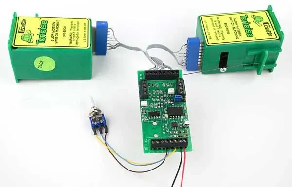
The Wabbit is a dual DCC accessory decoder designed to operate two Tortoise switch machines independently. It allows turnouts to be controlled from a DCC throttle, pushbuttons, or toggle switches.
Its Auto-Throw feature can automatically align a turnout when a train approaches against the points. A metal wheel bridges an isolated trigger-rail gap, signaling the Wabbit to move the Tortoise and set a safe route.
Main point
Correct Wabbit J2 terminal assignments are only part of the Wabbit Auto Throw installation process. Auto-Throw also requires the auxiliary contacts inside the Tortoise to switch DCC track power between the Clear and Throw trigger rails as the turnout moves.
What Auto Throw Does
Auto-Throw protects a trailing-point movement. If a train approaches a turnout against the points, a metal wheel bridges an isolated trigger-rail gap to the adjacent powered rail. This momentarily places DCC on both Wabbit trigger inputs. The Wabbit responds by driving the Tortoise to align the turnout for the approaching train.
This is not conventional block occupancy detection. The Wabbit is looking for a specific electrical condition created by the trigger rails, the Tortoise auxiliary contacts, and a metal wheel bridging a gap.
The Three Separate Circuits
| Circuit | Switch B example | Purpose |
| Motor drive | J2-7 and J2-8 to Tortoise pins 1 and 8 | Moves the Tortoise motor and turnout points. |
| Trigger inputs | J2-3 Clear and J2-4 Throw | Lets the Wabbit sense the Auto-Throw condition. |
| Power routing | Tortoise auxiliary contacts pins 2 through 7 | Switches DCC track power to the trigger rail that matches the present turnout position. |
Why the Tortoise Contacts Are Necessary
The Tortoise motor terminals and its auxiliary switch contacts serve different jobs. Pins 1 and 8 run the motor. The Tortoise contacts on pins 2 through 7 form two mechanically operated changeover switches. They move whenever the Tortoise moves, so they provide feedback about the turnout position by routing power to the appropriate trigger rail.
The Tortoise contacts do not send a separate digital position message to the Wabbit. Instead, they arrange the track circuit so that one Wabbit trigger input is already powered and the other is normally unpowered. A wheel entering from the route that is not aligned supplies power to the second input by bridging the gap. When both inputs are powered at once, the Wabbit changes the turnout.
Required Trigger Rail Power Sequence
| Turnout position | Clear trigger rail | Throw trigger rail |
| Clear | Powered | Not powered |
| Thrown | Not powered | Powered |
If both trigger rails are powered continuously, or neither rail changes state when the turnout moves, Auto-Throw cannot operate as designed. The trigger rails must not have independent track feeders that bypass the Tortoise contacts.
Switch A and Switch B Terminal Assignments
| Function | Switch A | Switch B | Connection |
| Clear trigger | J2-1 | J2-3 | Clear trigger rail circuit |
| Throw trigger | J2-2 | J2-4 | Throw trigger rail circuit |
| Tortoise motor | J2-5 and J2-6 | J2-7 and J2-8 | Tortoise pins 1 and 8 |
Caution DCC input power belongs only on Wabbit J1-7 and J1-8. Connecting DCC input power to the motor outputs can damage the decoder.
Switch A Wiring Example
Switch B Wiring Example
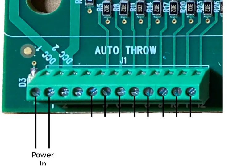
Figure 2 Switch B Auto-Throw wiring showing the Wabbit trigger inputs motor outputs and Tortoise auxiliary contacts
Follow the complete current path in the diagram. J2-3 and J2-4 connect to the Clear and Throw trigger circuits. J2-7 and J2-8 drive Tortoise pins 1 and 8. The red and green wires through the Tortoise contacts route DCC to only the trigger rail appropriate for the present point position.
Operating Sequence
Turnout is Clear The Tortoise contacts power the Clear trigger rail. The Throw trigger rail remains unpowered.
Train approaches on the Clear route A wheel bridges the Clear gap, but that trigger circuit is already powered. No command is generated and the turnout stays Clear.
Train approaches on the Throw route A wheel bridges the unpowered Throw trigger rail to the adjacent powered rail. DCC is now present on both Wabbit trigger inputs.
Wabbit throws the turnout The Wabbit drives the Tortoise. As the motor moves, its contacts transfer power: the Throw trigger rail becomes powered and the Clear trigger rail becomes unpowered.
Trigger Rail Construction
Each trigger rail is a short isolated rail section located on an approach to the frog. Its length may be selected to suit the installation. Depending on frog construction, one or two insulating gaps may be required. The isolated rail must be connected to the correct Wabbit trigger input and powered only through the Tortoise contact arrangement shown in the manual.
Figure 2 Example of a short trigger rail isolated by gaps at both ends
A locomotive may continue to run across an unpowered trigger section because multiple wheels or trucks can bridge the section. Continued movement by itself does not prove that the trigger rail is continuously powered.
Troubleshooting Auto Throw
Confirm the correct half of the Wabbit. For Switch B, use J2-3 and J2-4 for the trigger circuits and J2-7 and J2-8 for the Tortoise motor.
Confirm that each trigger rail is physically isolated at the required gap or gaps.
Verify there is no separate feeder connected directly to an isolated trigger rail.
With the turnout Clear, measure DCC voltage from each trigger rail to the opposite continuous rail: the Clear trigger rail should be powered and the Throw trigger rail should not be powered.
Throw the turnout and measure again using the same reference rail: the Throw trigger rail should now be powered and the Clear trigger rail should not be powered.
If that power sequence does not reverse, trace the wiring through the Tortoise auxiliary contacts and verify the correct contact common and switched terminals.
Manually bridge the appropriate trigger-rail gap to the adjacent powered rail with a metal screwdriver or jumper. This duplicates the wheel contact.
If manual bridging operates the turnout, the Wabbit and Tortoise circuits are responding; inspect wheel contact, gap placement, rail cleanliness, and trigger length.
If manual bridging does not operate the turnout, recheck the J2 trigger connections, Tortoise contact wiring, DCC power, and Wabbit programming.
Power District Considerations
For initial testing, power the Wabbit and the associated turnout area from the same DCC district. This removes district phasing and boundary behavior as variables. After the circuit operates correctly, any final multi-district arrangement must preserve the required DCC relationship at the trigger inputs and comply with the layout power-management design.
Common Misunderstandings
The Wabbit senses occupancy It does not use conventional occupancy detection. It responds when a wheel bridge creates DCC on both trigger inputs.
J2 trigger wires are sufficient They are not. The Tortoise auxiliary contacts must switch track power between the trigger rails.
The Tortoise contacts connect to the motor output The motor uses pins 1 and 8. The auxiliary contacts on pins 2 through 7 are a separate switching circuit.
A train running across the gaps proves the rail is fed Not necessarily. Long wheelbases and multiple pickups can carry power across an isolated section.
Reference and Source Notes
Technical basis: The Wabbit REV III installation instructions dated May 20 2011, especially pages 5 through 7, and clarification from Larry Maier, designer of the Wabbit. The supplied customer installation photographs were used as a troubleshooting example.
Terminology follows the manual: Clear means the normal route and Thrown means the alternate or reverse route. The installation must be verified against the turnout orientation, frog type, Tortoise orientation, and programming used on the layout.