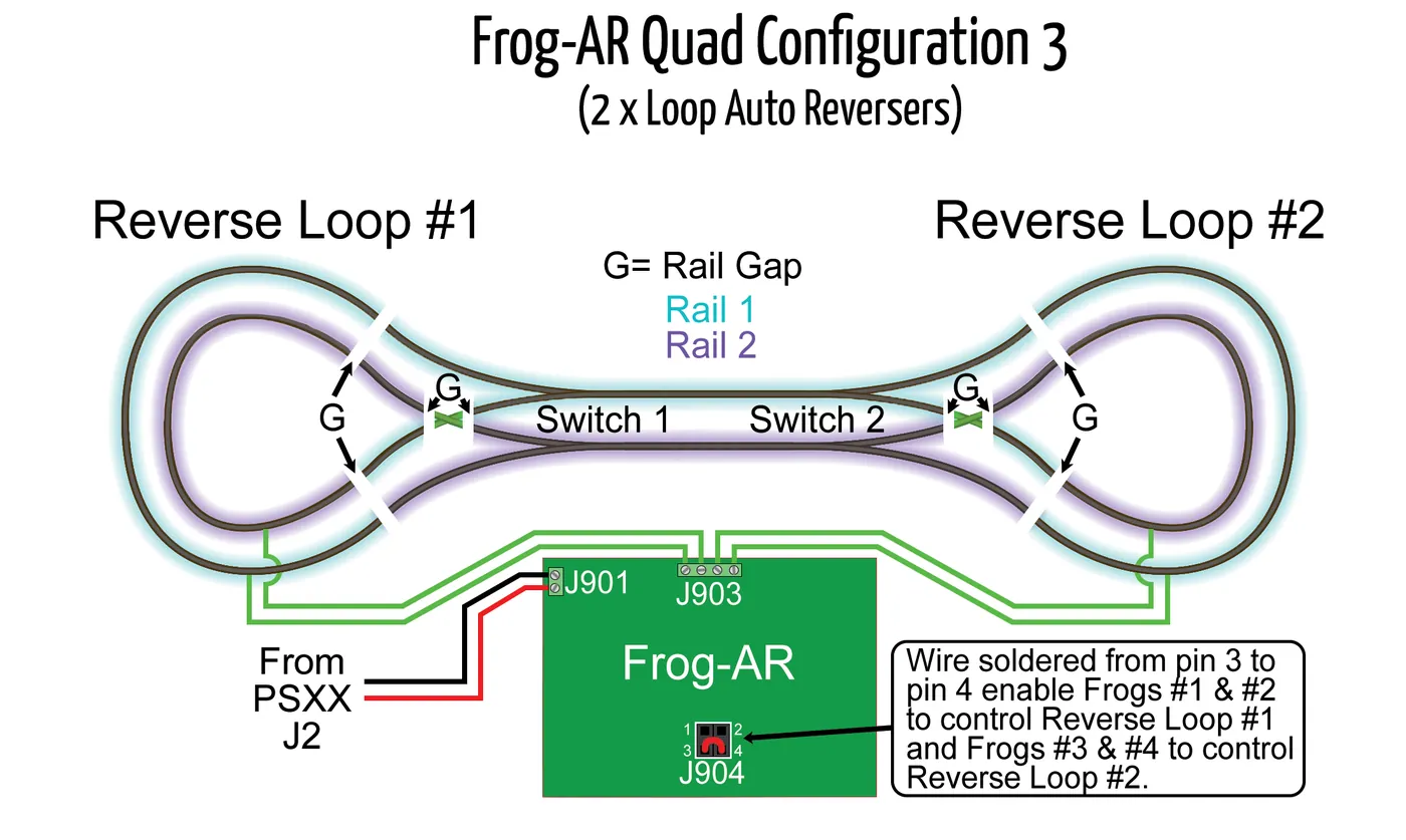
Reverse loops are one of the most common sources of confusion when wiring a DCC layout. A track plan can look perfectly straightforward mechanically, yet electrically contain several locations where the rails reconnect with opposite phase.
The good news is that DCC makes handling these situations relatively simple. You don't have to manually flip toggle switches or worry about changing the direction of the locomotive. What you need to do is:
- Identify each reversing section.
- Electrically isolate it from the surrounding railroad.
- Feed that section through an automatic reverser.
- Divide the remaining layout into sensible protected power districts.
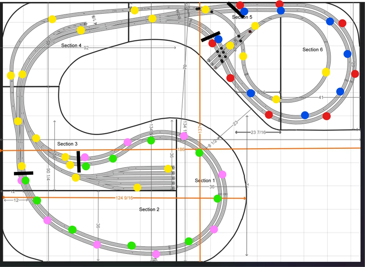
At Tony's Train Exchange, we recently reviewed a customer's track plan that provides an excellent example. At first glance, the layout appears to contain a few interconnected loops. Electrically, however, we identified four separate reversing districts plus one conventional power district.
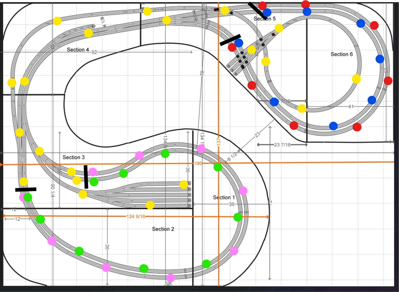
For this particular layout, our recommendation is:
- Red reverse district — Frog-AR Quad #1
- Blue reverse district — Frog-AR Quad #1
- Pink reverse district — Frog-AR Quad #2
- Green reverse district — Frog-AR Quad #2
- Yellow normal district — PSXX circuit breaker
This approach allows the four reversing districts to be handled with only two DCC Specialties Frog-AR Quad boards, while the conventional portion of the railroad is protected by a DCC Specialties PSXX.
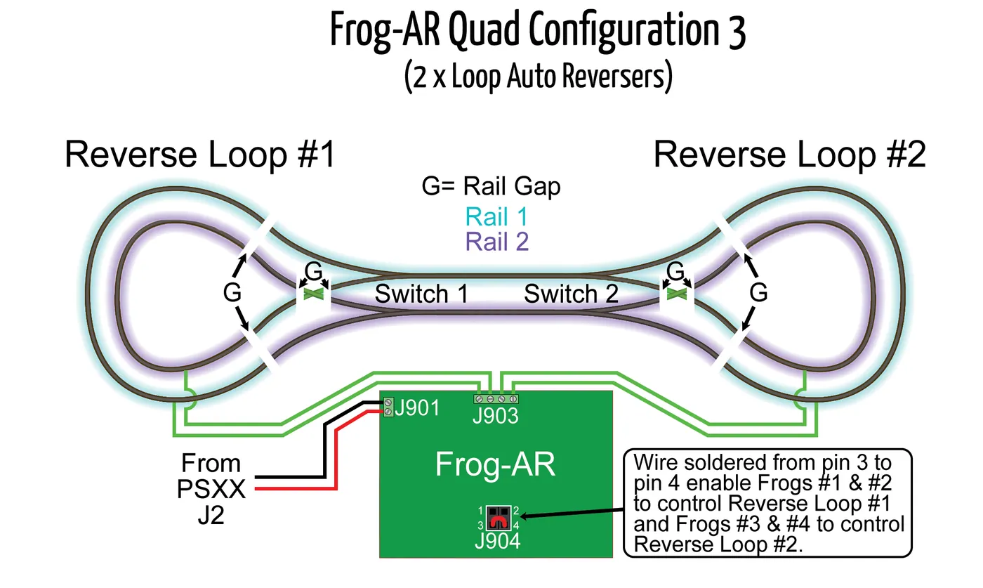
Frog-AR Articles
PSXX Articles
First: What Creates a Reverse Loop?
A DCC reverse loop is fundamentally an electrical problem, not a train-direction problem.
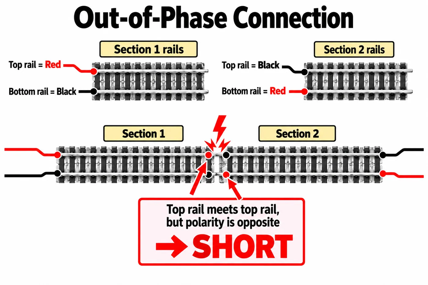
Imagine following one rail around the railroad. If the track arrangement eventually allows that rail to connect to the opposite rail, you have created a reversing section.
This commonly occurs with:
- Balloon tracks
- Turning loops
- Wyes
- Reverse crossovers
- Dogbone layouts
- Diagonal connections between mainlines
- Complex junctions
- Return loops in staging yards
Without electrical isolation, the two rails eventually meet with opposite DCC phase and create a direct short circuit.
DCC does not eliminate this electrical problem. What DCC does allow us to do is solve it automatically.
How an Automatic DCC Reverser Works
An automatic reverser powers an electrically isolated section of track.
When a locomotive or conductive wheelset crosses the boundary between the normal district and reversing district, the reverser determines whether the phase of the reversing section matches the adjoining track.
If it does, nothing needs to happen.
If it does not, the wheels bridging the boundary create a momentary phase mismatch. The electronic reverser detects that condition and switches the phase of the entire reversing section.
This happens fast enough that the locomotive normally continues through the boundary without stopping.
The locomotive decoder does not care that the rail phase underneath it changed. The decoder continues controlling locomotive direction according to its DCC commands.
That distinction is important:
The auto reverser is changing track phase. It is not reversing the locomotive.
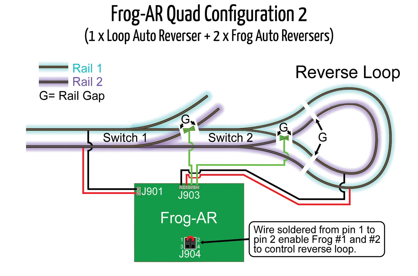
The Most Important Rule: Completely Isolate the Reversing District
Every reversing district must be electrically isolated from the surrounding railroad.
That means both rails must be gapped at every entrance and exit from the reversing section.
Do not feed the isolated reversing section from the regular track bus.
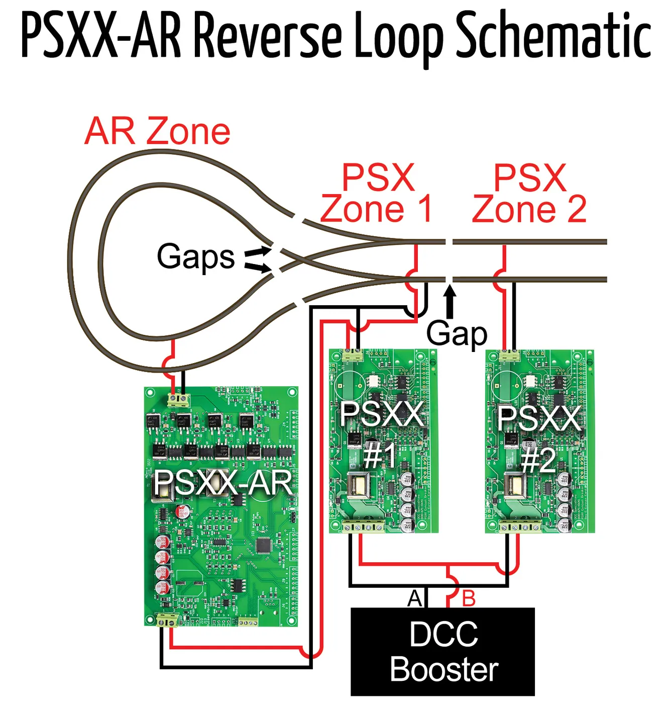
Instead, think of the electrical path this way:
DCC Booster → Auto Reverser → Isolated Reverse District
The output of the auto reverser becomes the track bus for that reversing section.
Feeders within the reversing section should connect to that bus rather than to the main layout bus.
Why We Recommend Staggering the Gaps
We generally recommend staggering the gaps between the two rails rather than placing the gaps directly opposite one another.
A stagger of approximately 3/4 inch is a good target.
The reason isn't mechanical—it is electrical.
Perfectly aligned gaps can, under certain circumstances, create a short in a way that causes the circuit protection to respond instead of allowing the reversing electronics to properly recognize the phase mismatch.
The stagger does not need to be exactly 0.750 inches. The objective is simply to avoid making the gaps perfectly aligned.
For additional information, see our Tony's Tip:
PSXX & PSXX-AR Reverse Loop Gap Spacing — Reason for the 0.75" Offset
Make the Reverse District Longer Than Your Longest Train
There is another extremely important design consideration:
The reversing section should be longer than the longest electrically continuous train that will occupy it.
Why?
Because you don't want conductive wheels simultaneously bridging both ends of the reversing section.
This becomes especially important with modern passenger trains.
A locomotive isn't necessarily the only piece of equipment picking up track power. You may also have:
- Lighted passenger cars
- Sound-equipped cars
- Caboose lighting
- End-of-train devices
- Multiple locomotives
- Consists with locomotives at both ends
All of these can potentially bridge electrical boundaries.
When designing the reversing section, therefore, don't think only about locomotive length. Think about the electrical footprint of the entire train.
Our Example: Four Reverse Districts
In the layout we're using for this example, we identified four areas that should be treated as independent reversing sections.
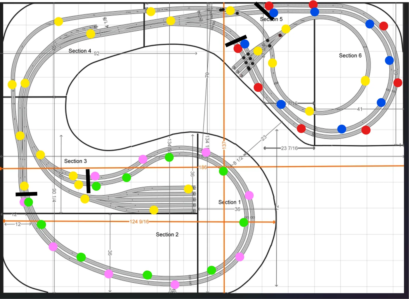
For clarity, we've identified them by color:
Red District
Reverse District #1
Blue District
Reverse District #2
Pink District
Reverse District #3
Green District
Reverse District #4
The yellow section does not reverse track phase and therefore does not require an auto reverser.
That gives us:
4 reversing districts + 1 conventional district
At first glance, you might assume this requires four separate auto-reverser boards.
There is a more efficient solution.
Using the Frog-AR Quad for Multiple Reverse Districts
The DCC Specialties Frog-AR Quad is an unusually flexible DCC power-management device.
Most modelers associate the Frog-AR family with automatic frog polarity control. However, the Quad can be configured for applications beyond simply controlling individual turnout frogs.
For this layout, we can configure two Frog-AR Quad boards to handle the four independent reversing districts.
The arrangement becomes:
Frog-AR Quad #1
Reverse Controller A → Red District
Reverse Controller B → Blue District
Frog-AR Quad #2
Reverse Controller A → Pink District
Reverse Controller B → Green District
The result is a clean and centralized installation:
Two boards → Four independently controlled reverse districts
This is considerably cleaner than scattering four separate reversing devices around the railroad.
What About the Yellow District?
The yellow portion of the railroad does not create a reversing condition.
It therefore does not need an auto reverser.
It should instead be treated as a conventional protected DCC power district.
For this section, we recommend a:
DCC Specialties PSXX Circuit Breaker
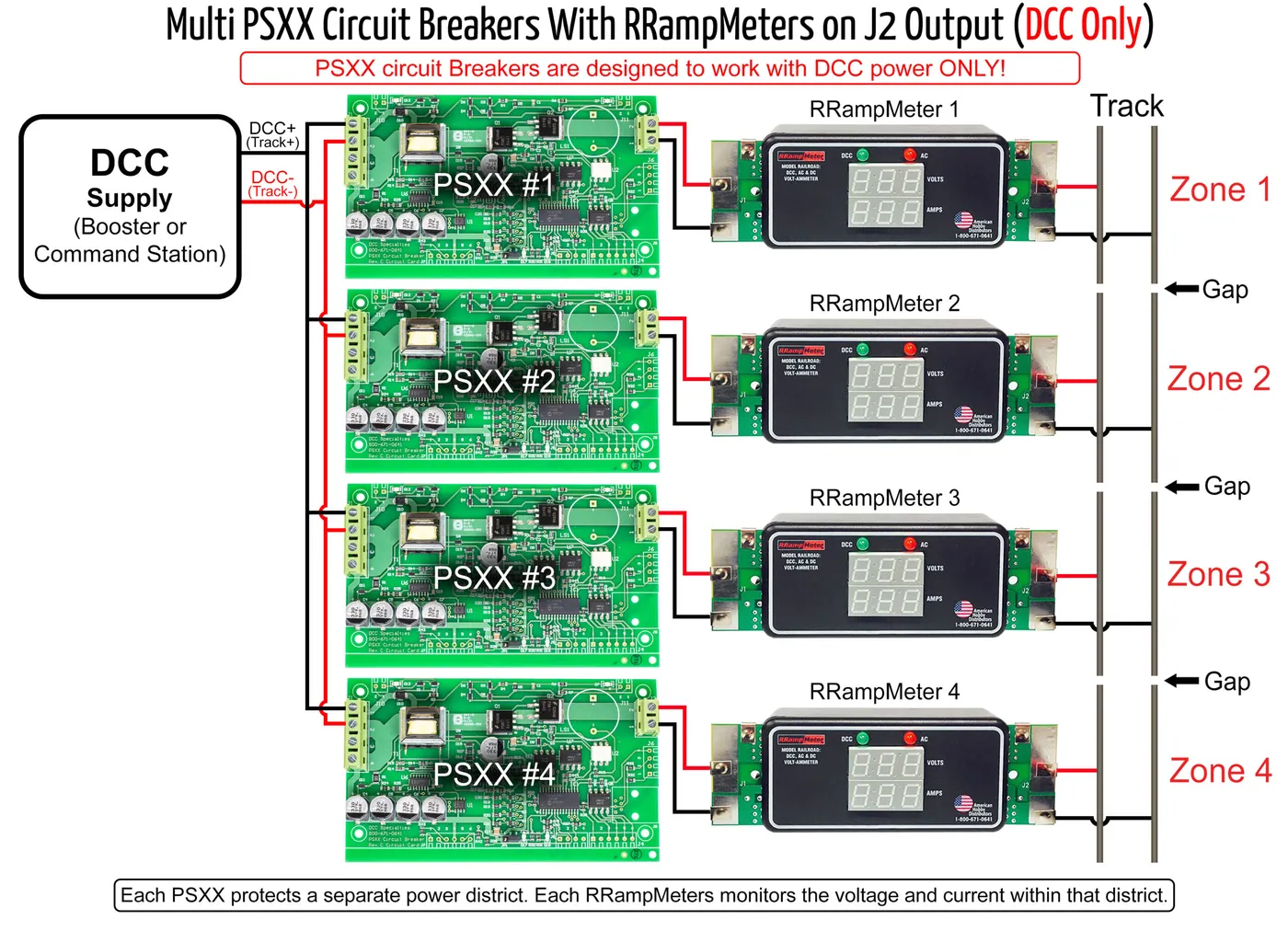
The basic electrical arrangement becomes:
DCC Booster → PSXX → Yellow District
The PSXX provides electronic short-circuit protection and active current limiting for the conventional portion of the railroad.
Why Use a Circuit Breaker if the Booster Already Has One?
Virtually every modern DCC booster has internal short-circuit protection.
That does not mean the entire layout should be connected directly to the booster.
The booster's protection is essentially the last line of defense for the entire system.
District-level circuit breakers allow the layout to be segmented.
For example, suppose a locomotive derails and shorts the rails in the yellow district.
Without district protection:
Yellow district shorts → Booster trips → Entire railroad stops
With a PSXX:
Yellow district shorts → PSXX responds → Yellow district is affected while the rest of the layout can remain operational
This becomes increasingly valuable as layouts become larger and more complex.
Why We Recommend the PSXX
The PSXX operates differently from many conventional electronic circuit breakers.
Instead of simply allowing the full available fault current to flow until the breaker decides to shut down, the PSXX incorporates active current limiting.
When a short occurs, the PSXX immediately begins controlling the available fault current before ultimately shutting down the affected district if necessary.
That can help reduce:
- Fault energy
- Arcing
- Rail pitting
- Booster interaction
- Stress on wiring
- Stress on locomotive decoders
This is particularly valuable on today's layouts with sound-equipped locomotives, lighting and keep-alive capacitors.
For a deeper explanation, see our article:
PSX vs. PSXX Circuit Breakers: Why the PSXX Represents a Major Step Forward
Power Districts and Reverse Districts Are Not the Same Thing
These two terms are sometimes used interchangeably, but they describe different electrical functions.
Power District
A power district is a section of railroad separated for electrical protection or power management.
A PSXX is an example of a device used to protect such a district.
Reverse District
A reverse district is an isolated section in which the rail phase must be capable of changing automatically to prevent a short when trains cross its boundaries.
An auto reverser controls that section.
Therefore:
Every reverse district is an electrically isolated district, but not every power district is a reversing district.
That distinction becomes very important when planning a complicated railroad.
One Booster Can Still Have Multiple Districts
Another common misconception is that every power district requires another booster.
It doesn't.
You can divide the output of one DCC booster into several separately protected districts.
Conceptually:
DCC Booster
↓
Power Distribution
↙ ↓ ↓ ↘
PSXX / Reverse Controller / Reverse Controller / PSXX
↓ ↓ ↓ ↓
District A / District B / District C / District D
The circuit breakers and auto reversers divide and manage the booster output.
They do not necessarily increase the amount of power available.
If the railroad eventually requires more current than the original booster can supply, that is when an additional booster becomes appropriate.
Don't Add Boosters Just Because You Have a Large Track Plan
Track mileage does not determine booster requirements.
Electrical load does.
A large layout with two locomotives operating may require less current than a relatively small layout with:
- Ten sound locomotives
- Lighted passenger cars
- Multiple consists
- Stationary decoders
- Accessories powered from the track bus
Before adding boosters, determine how much current the railroad actually uses.
This is why we frequently recommend using an RRampMeter when designing or troubleshooting DCC power distribution.
The RRampMeter lets you measure what the layout is actually doing instead of estimating.
See our guide:
RRampMeter + PSXX — The Complete Guide to DCC Power Management
Recommended Wiring Architecture for This Layout
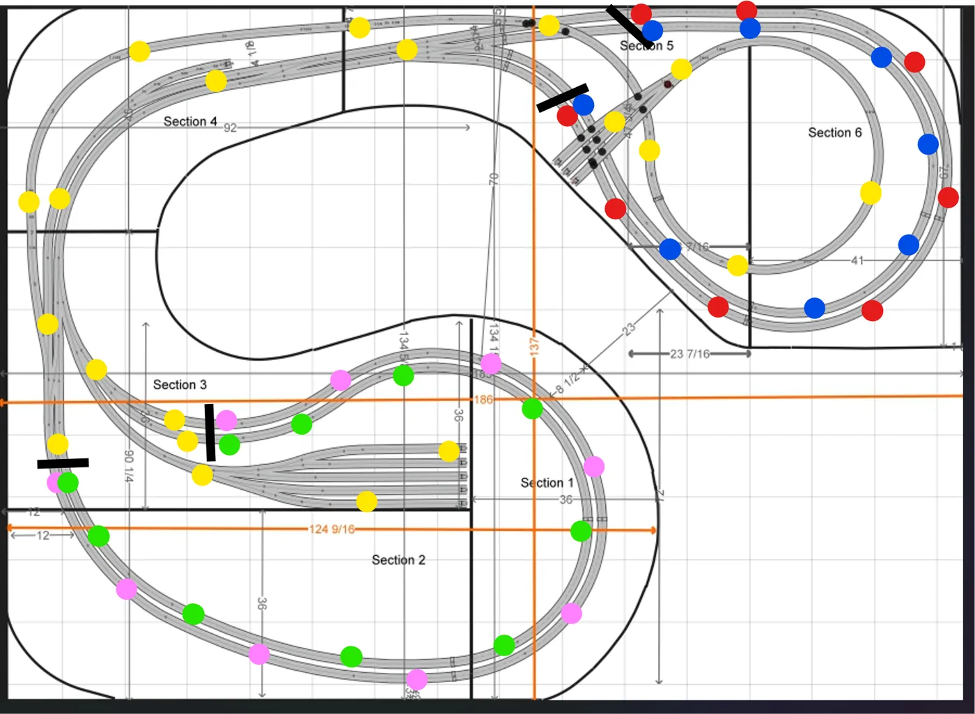
For our example layout, the basic architecture would look like this:
DCC Command Station / Booster
↓
DCC Power Bus
↓
Distribution Point
From that distribution point:
Branch 1
Frog-AR Quad #1
→ Red Reverse District
→ Blue Reverse District
Branch 2
Frog-AR Quad #2
→ Pink Reverse District
→ Green Reverse District
Branch 3
PSXX
→ Yellow Normal District
Each colored district has its own feeders.
The red feeders go only to the red district.
The blue feeders go only to the blue district.
The pink feeders go only to the pink district.
The green feeders go only to the green district.
The yellow feeders go only to the yellow district.
Do not accidentally connect feeders from two different districts to the same section of track.
That defeats the electrical isolation and is one of the most common causes of mysterious reverse-loop problems.
Label Your Wiring
On a layout with five electrical districts, labeling becomes extremely valuable.
We recommend labeling:
- Both ends of each bus
- Frog-AR outputs
- PSXX input and output
- Terminal strips
- District boundaries
- Feeder groups
If you're already using colors on your track diagram, continue those colors underneath the layout.
For example:
RED BUS — Reverse District 1
BLUE BUS — Reverse District 2
PINK BUS — Reverse District 3
GREEN BUS — Reverse District 4
YELLOW BUS — PSXX District
Six months from now, that labeling will be much more useful than trying to remember where every wire goes.
Test One District at a Time
Do not wire the entire layout and then turn everything on for the first time.
Commission the railroad systematically.
We recommend:
- Connect the DCC booster.
- Verify booster output.
- Connect the PSXX district.
- Test the yellow district.
- Connect Frog-AR Quad #1.
- Test the red district.
- Test the blue district.
- Connect Frog-AR Quad #2.
- Test the pink district.
- Test the green district.
- Test every reverse-district boundary individually.
- Finally, run complete trains through every possible route.
This makes troubleshooting dramatically easier.
If something goes wrong immediately after connecting the blue district, for example, you know where to start looking.
Common Reverse Loop Wiring Mistakes
Most auto-reverser problems are not caused by the auto reverser.
They're caused by the layout wiring.
Here are some of the first things we check when troubleshooting.
1. Only One Rail Was Gapped
A reversing section normally needs complete two-rail isolation.
Gap both rails at the district boundaries.
2. A Feeder Bypasses the Auto Reverser
This is extremely common.
The track may be correctly gapped, but one feeder inside the reversing section is accidentally connected to the main track bus.
That feeder electrically bypasses the reverser.
Every feeder inside the reverse district must come from that district's reversing output.
3. Two Reverse Districts Are Accidentally Connected
With several reverse districts in close proximity, carefully check crossovers, turnouts and feeders.
An unintended electrical connection can effectively join two districts together.
4. The Reverse Section Is Too Short
Long trains—especially lighted passenger trains—can bridge both ends of a reversing section.
Design the section around the longest electrically active train you expect to operate.
5. The Booster Trips Before the Reverser Can Respond
The auto reverser must be able to resolve the phase mismatch before upstream protection shuts everything down.
Proper breaker/reverser coordination is important on more complex DCC systems.
6. The Problem Is Actually a Turnout Short
Not every short near a reverse-loop boundary is caused by reversing polarity.
Incorrect frog wiring, turnout contacts or wheel backs contacting opposite-polarity rails can create a completely different type of short.
An auto reverser cannot fix a genuine track-wiring fault.
Don't Use Auto Reversers to Hide Wiring Problems
This deserves special emphasis.
An automatic reverser is designed to correct a legitimate rail-phase mismatch.
It should not be used as a band-aid for:
- Incorrectly wired turnouts
- Miswired frogs
- Crossed feeders
- Inadequate track gaps
- Metal wheels bridging improperly designed electrical boundaries
If an auto reverser repeatedly cycles or a circuit breaker continually trips, investigate the underlying electrical condition.
Plan the Electrical Layout Before Installing the Boards
Before purchasing or installing DCC power-management hardware, take a copy of your track plan and mark the electrical districts.
Color coding works particularly well.
For every suspected reversing section, ask:
If I follow one rail through this route, can it eventually reconnect to the opposite rail?
If the answer is yes, you have found a reversing condition.
Then identify where you can place the two-rail gaps so that the reversing section:
- Is completely isolated
- Has logical entrance and exit points
- Is long enough for your trains
- Can have its own dedicated feeders
- Does not create unnecessary electrical complexity
Doing this work on paper is much easier than discovering the problem after the track has been ballasted.
The Final Recommendation for Our Example Layout
For the layout shown in this example, we recommend:
| District | Type | Recommended Protection |
|---|---|---|
| Red | Reverse District | Frog-AR Quad #1 |
| Blue | Reverse District | Frog-AR Quad #1 |
| Pink | Reverse District | Frog-AR Quad #2 |
| Green | Reverse District | Frog-AR Quad #2 |
| Yellow | Normal Power District | PSXX |
This gives the railroad four independently controlled reversing sections and one conventionally protected power district without unnecessarily complicating the installation.
The Bottom Line
Complex DCC track plans become much easier to understand once you stop looking at them strictly as track diagrams and start looking at them as electrical districts.
For this layout, what initially appears to be a complicated collection of interconnected loops breaks down neatly into:
Four reverse districts + one conventional district.
Our solution is equally straightforward:
Two Frog-AR Quads handle the four reversing districts.
One PSXX protects the conventional yellow district.
The keys to reliable operation are proper two-rail isolation, sensible gap placement, dedicated feeders for every district and making sure each reversing section is long enough for the trains that will use it.
When those fundamentals are correct, DCC automatic reversing can be remarkably transparent—the train simply crosses the boundary and keeps running.
Additional Tony's Train Exchange Resources
DCC Specialties Frog-AR Quad Configuration Guide
PSXX Wiring Diagrams & Compatibility
PSXX & PSXX-AR Reverse Loop Gap Spacing
PSX vs. PSXX Circuit Breakers: Why PSXX Represents a Major Step Forward
RRampMeter + PSXX — The Complete Guide to DCC Power Management
Shop DCC Circuit Breakers & Auto Reversers Tony's Train Exchange has specialized in Digital Command Control, DCC power management, decoder installations and model railroad electronics since 1991. If you're unsure whether your track plan contains a reverse loop, wye or other reversing section, send us your track plan and we'll help you determine the appropriate DCC power-management solution.