Reverse-loop problems can be deceptive. A wiring mistake may actually make a layout appear to work correctly, masking the real problem until another change exposes it.
This Tony’s Tips case study follows a particularly useful PSXX-AR troubleshooting example. The PSXX-AR itself tested correctly, yet a locomotive continued to cause a persistent short when crossing one end of the reversing section.
Ultimately, the problem wasn't the PSXX-AR at all. It was a tiny piece of rail bridging an insulating gap — small enough that it was barely visible.
The solution demonstrates why systematic electrical testing is often more reliable than visual inspection when troubleshooting DCC reverse loops.
The Original Problem
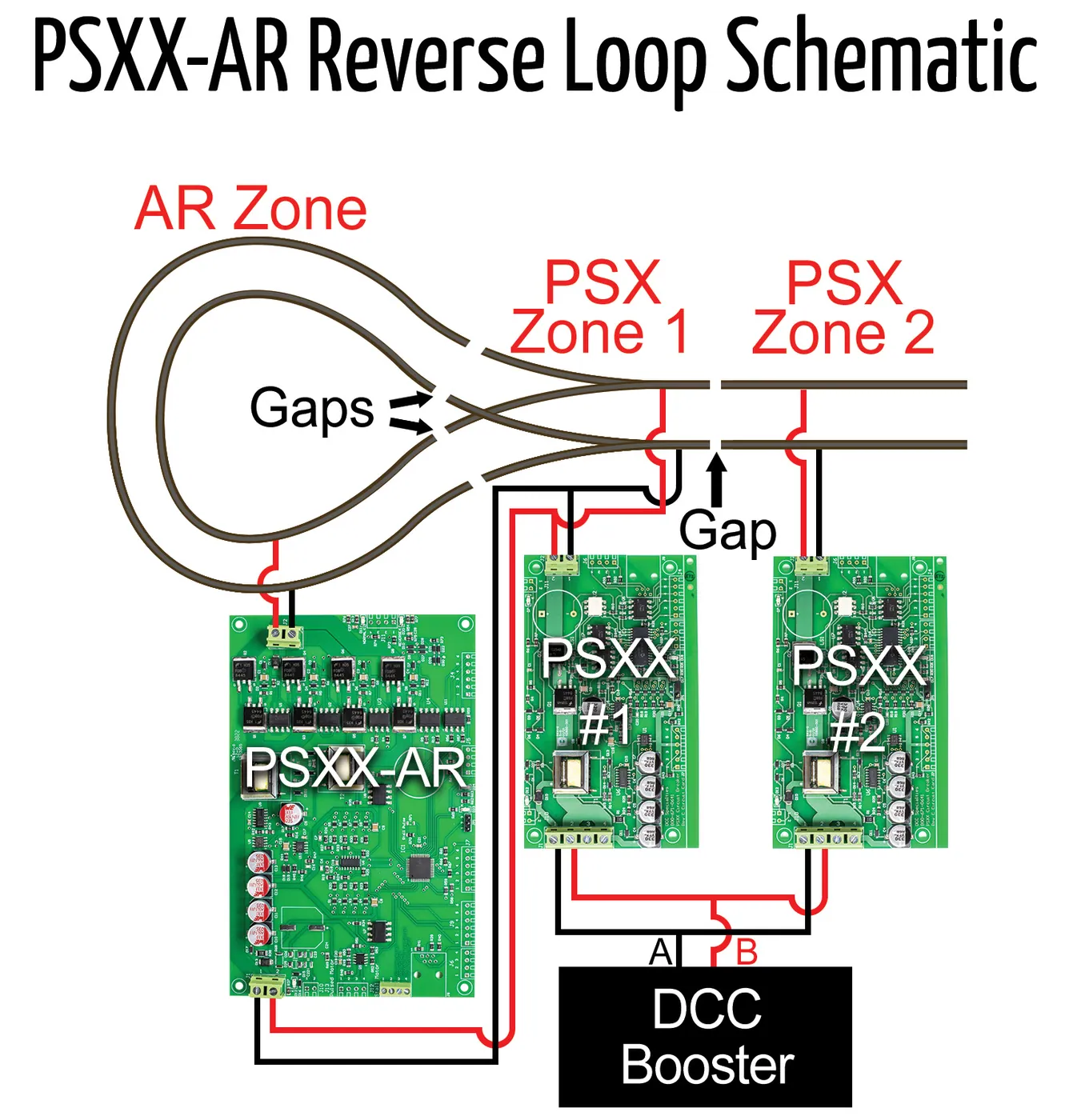
The layout contained a return loop protected by a DCC Specialties PSXX-AR. The track outside the reversing section was part of Zone 1, protected by a PSXX circuit breaker.
The customer initially had insulated rail joiners immediately at the turnout as well as gaps approximately two feet farther down the track.
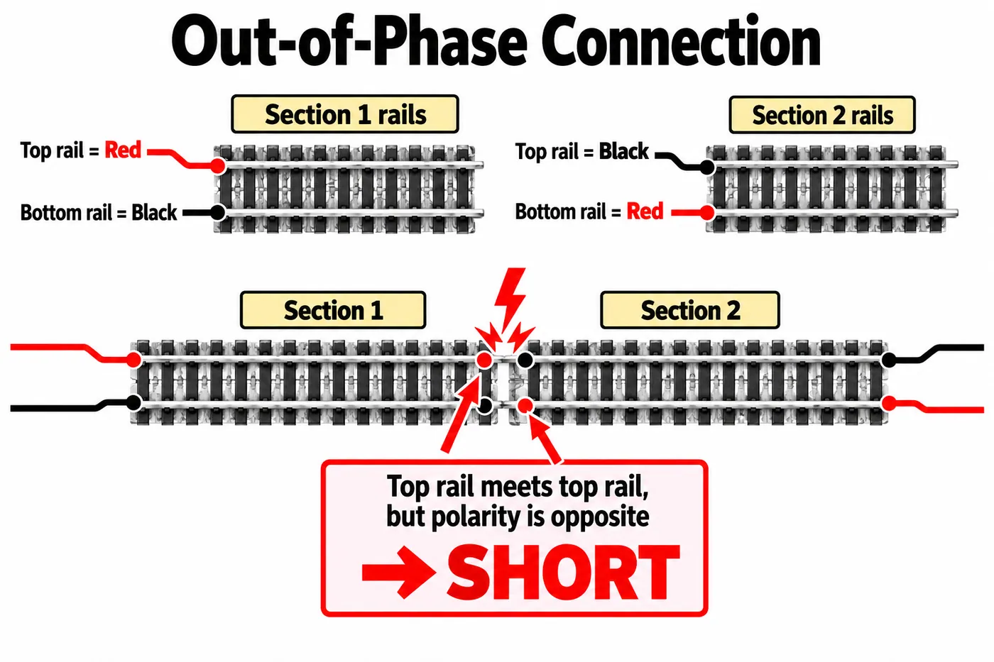
Complicating matters, the feeders in that two-foot section had accidentally been connected with their rail orientation reversed relative to Zone 1.
The following Shows the rails between the gaps as incorrectly wired to the PSXX
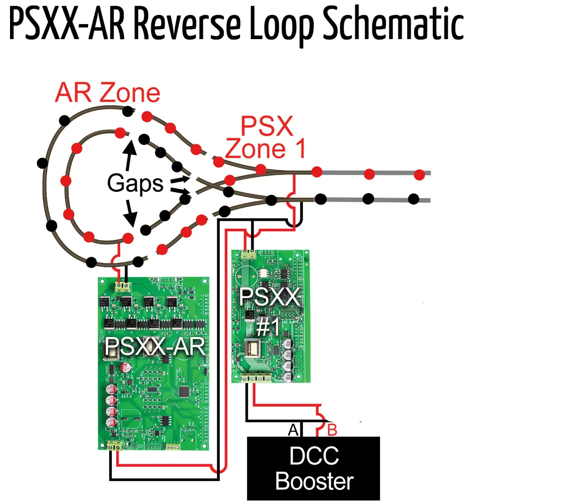 The Above is incorrectly wired
As the customer explained after discovering the mistake, he had soldered feeders while working his way around the loop. By the time he reached the exit leg, the feeders were still aligned with the return loop but were misaligned with Zone 1.
The Loop should have been wired like this:
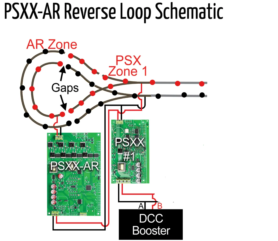
This created an important troubleshooting lesson:
A wiring error can sometimes mask another wiring error.
The locomotive appeared to travel successfully around the loop, giving the impression that the PSXX-AR was reversing the track polarity. In reality, the locomotive was simply continuing on track that happened to have the same electrical orientation as the return loop.
Because the turnout was also insulated, the underlying problem wasn't immediately apparent.
Correcting the First Wiring Problem
The customer corrected the feeder orientation and removed the unnecessary insulated joiners at the turnout.
The resulting arrangement was:
Zone 1 → turnout → approximately two feet of Zone 1 track → double gaps → PSXX-AR reversing section
The track between the turnout and the gaps was now powered by Zone 1 and properly aligned with the Zone 1 rails.
The return loop beyond the gaps was powered from the J2 output of the PSXX-AR.
Both rails of the reversing section were supposed to be completely isolated at the gaps.
At least, that's how they appeared visually.
As the customer explained after discovering the mistake, he had soldered feeders while working his way around the loop. By the time he reached the exit leg, the feeders were still aligned with the return loop but were misaligned with Zone 1.
The Loop should have been wired like this:
A New Symptom Appears
With the initial feeder problem corrected, the locomotive could enter and travel around the reverse loop.
However, when it reached the gaps at the exit, the layout shorted.
More importantly, the short stayed shorted.
The customer also reported that the PSXX-AR did not appear to reverse the track polarity or operate the associated Tortoise turnout motor.
At first glance, this could easily lead to the conclusion that the PSXX-AR's auto-reversing circuitry was malfunctioning.
But we already had an important piece of information.
Test the PSXX-AR Separately From the Layout
Earlier troubleshooting had demonstrated that the PSXX-AR could correctly reverse its J2 output.
The PSXX-AR switches both rails of its output. In its normal state:
J1-1 → J2-1
J1-2 → J2-2
When reversed:
J1-1 → J2-2
J1-2 → J2-1
The PSXX-AR manual also specifies that both rails of the reverse loop must be isolated from the rest of the layout. It is not intended for common-rail wiring.
Once testing establishes that the PSXX-AR itself can switch polarity correctly, repeatedly changing settings or replacing the PSXX-AR is unlikely to identify a layout wiring problem.
Instead, the next question should be: Is the reversing section really electrically isolated?
The Critical Question: Does the Short Clear?
We asked the customer:
When the locomotive crosses the gap, does the PSXX-AR short briefly and recover, or does it short and stay shorted?
The answer was:
It shorts and stays shorted.
That distinction was extremely useful.
An auto-reverser detects the phase mismatch that occurs when metal wheels bridge two electrically opposite track sections and rapidly switches the electrical orientation of the reversing section.
Under normal operation, this occurs quickly enough that the locomotive simply continues across the boundary.
A persistent short suggests something different.
Since the PSXX-AR had already been independently tested and demonstrated that it could reverse correctly, the persistent short pointed us back toward the layout wiring and electrical isolation of the reversing section.
Don't Assume Two Adjacent Reverse Loops Are the Problem
This layout also had another PSXX-AR-powered return loop adjacent to the same Zone 1 PSXX district.
The customer wondered whether having two reversing sections adjoining the same Zone 1 district could be causing the problem.
It should not.
Multiple properly isolated reversing sections can border the same non-reversing power district. Each PSXX-AR controls the polarity of its own isolated reversing section.
The important requirement is that each reversing section is electrically isolated and receives its track power only through its respective PSXX-AR output.
Stop Running Trains and Test the Wiring
At this stage, continuing to run the locomotive across the gaps was providing little additional information.
We needed to test whether the reverse section was actually isolated.
Step 1 — Turn Off All DCC Power
Never perform continuity or resistance testing on powered track.
Turn the DCC system completely off.
Step 2 — Disconnect the PSXX-AR From the Reverse Section
Disconnect the J2 output wires from the reverse-section track bus.
This allows the reverse-section wiring to be tested independently of the PSXX-AR.
Step 3 — Remove Locomotives and Other Loads
Remove locomotives and any lighted or decoder-equipped rolling stock from the section being tested.
Decoders, lighting circuits and other electronic devices can provide resistance paths between the rails and produce confusing meter readings.
What Is a Continuity Meter?
You do not need a specialized continuity meter.
Most ordinary digital multimeters include a continuity-test function, usually identified by a buzzer or sound-wave symbol.
Touch the two meter probes together.
The meter should beep and normally indicate resistance close to 0 ohms (Ω).
In simple terms:
Beep / approximately 0 Ω = electrical connection
No beep / OL / very high resistance = open circuit
If your meter doesn't have a continuity setting, use the resistance (Ω) setting instead.
Test 1 — Check Between the Two Rails
With the PSXX-AR J2 output disconnected, place one probe on one rail of the reversing section and the other probe on the opposite rail.
Under normal conditions, the meter should not indicate direct continuity between the two rails.
If it does, there is an unwanted electrical connection somewhere.
Possible causes include:
- Crossed feeders
- Miswired track bus connections
- Incorrect turnout or frog wiring
- Accessory connections
- Hidden feeders
- Wiring left over from an earlier configuration
- Conductive material bridging an insulating gap
That last possibility turned out to be particularly important in this case.
Test 2 — Check Across Every Reversing-Section Gap
Next, test each insulating gap individually.
Place one probe on the Zone 1 side of the gap and the other probe on the reverse-loop side of that same rail.
There should be no continuity across the gap.
Repeat the test for the other rail and then perform the same tests at the opposite boundary of the reversing section.
If the meter indicates continuity across a gap, something is electrically bypassing it.
And that's exactly what happened here.
FOUND IT: The Actual Cause
The continuity testing led the customer back to the insulating gap.
On very close inspection, he discovered something that had been almost impossible to see:
A tiny piece of rail was stuck in the gap.
As the customer reported:
“FOUND IT! There was a small piece of rail stuck in the gap — I could barely see it. Cutting that fixed it.”
The gap appeared to be open when viewed normally, but the small piece of conductive rail was electrically bridging the two sections.
That meant the Zone 1 track and PSXX-AR reversing section were not actually isolated, even though visually they appeared to be.
Once the obstruction was removed and the gap was properly opened, the short disappeared and the reversing section operated correctly.
Why the PSXX-AR Couldn't Fix This Short
This distinction is important.
A PSXX-AR is designed to resolve the temporary phase mismatch that occurs when a locomotive bridges the boundary between a properly isolated reversing section and the adjoining track.
It cannot correct a reversing section whose isolation gap has been permanently electrically bridged.
The tiny piece of rail effectively defeated the electrical boundary between the two districts.
Changing the PSXX-AR's output polarity therefore could not eliminate the underlying electrical connection.
The PSXX-AR wasn't failing to do its job.
The reversing section wasn't actually isolated.
Why Visual Inspection Wasn't Enough
This case contained two separate problems that were difficult to identify visually.
First, the feeder orientation was incorrect.
Then, after correcting that problem, an almost invisible piece of rail remained across one of the isolation gaps.
Both problems reinforce the same lesson:
Electrical isolation should be tested electrically, not assumed visually.
A gap can look open and still conduct electricity.
Possible causes include:
- Metal rail fragments
- Conductive debris
- A gap that wasn't cut completely through the rail
- Rail expansion closing a previously adequate gap
- A feeder accidentally connected around the gap
- Turnout or frog wiring bypassing the gap
A multimeter doesn't care what the track looks like. It tells you whether an electrical path actually exists.
A Good Practice After Cutting DCC Isolation Gaps
This case suggests a simple procedure worth adding whenever you create a reverse loop, power district or other electrically isolated track section:
Test every gap for continuity before connecting the electronics.
After cutting the gaps:
- Turn off or disconnect track power.
- Remove conductive rolling stock from the area.
- Put the multimeter in continuity mode.
- Place one probe on each side of the gap on the same rail.
- Confirm that the meter shows an open circuit.
- Repeat for every isolation gap.
It takes only a few minutes and can prevent hours of troubleshooting later.
Also inspect freshly cut gaps carefully for metal filings, rail slivers or other conductive debris.
Don't Troubleshoot Secondary Symptoms Too Early
The customer also noted that the Tortoise wasn't changing position when the locomotive reached the gap.
That was useful information, but it wasn't the primary problem.
The first priority was establishing that:
- The reversing section was completely isolated.
- The PSXX-AR was correctly connected.
- The PSXX-AR could successfully reverse its output.
- A locomotive could cross both reversing-section boundaries without producing a persistent short.
Trying to troubleshoot the Tortoise at the same time would have added another variable to a problem that ultimately came down to a tiny piece of metal.
The Key Diagnostic Principle
This case illustrates one of our most useful rules for troubleshooting DCC power-management problems:
Separate the electronic device from the layout and test them independently.
The PSXX-AR passed its functional tests.
That was evidence that we should stop assuming the PSXX-AR was defective and investigate the layout itself.
The system can be broken down into:
Booster → circuit protection → PSXX-AR → reversing-section bus → feeders → track → isolation gaps
By testing each portion separately, a complicated DCC problem becomes a series of simple electrical questions.
In this case, one of those questions was:
Is this gap really electrically open?
The continuity meter answered the question.
It wasn't.
Tony's Tips: Quick PSXX-AR Troubleshooting Checklist
When a PSXX-AR reverse loop shorts and stays shorted:
- Don't assume the PSXX-AR is defective.
- Confirm independently that the PSXX-AR can reverse its output.
- Confirm that both rails of the reversing section are gapped.
- Verify that only the PSXX-AR J2 output powers the reversing section.
- Turn all DCC power OFF.
- Disconnect J2 from the reversing-section bus.
- Remove locomotives and other electronic loads from the track.
- Continuity-test between the two reversing-section rails.
- Continuity-test across every individual isolation gap.
- If a gap shows continuity, inspect it closely for rail slivers, metal debris or an incomplete cut.
- If the gaps test correctly, systematically disconnect feeders and other wiring until the unwanted electrical path is located.
- Reconnect the PSXX-AR only after the reversing section has been verified electrically isolated.
The Takeaway
The final fault in this case was remarkably small:
A nearly invisible piece of rail was bridging an isolation gap.
But the diagnostic lesson is much larger.
The customer initially had a feeder wiring error that masked the behavior of the reverse loop. After that was corrected, the persistent short appeared to implicate the PSXX-AR. Independent testing proved that the PSXX-AR was working correctly, so troubleshooting shifted back to the track.
A continuity test then exposed what visual inspection had missed.
If a PSXX-AR tests correctly but a reverse loop shorts and stays shorted, verify the electrical isolation of the reversing section before changing settings or replacing components.
And don't just look at the gaps.
Meter them.
Tony's Train Exchange